Cmos xor gate schematic 6: circuit diagram of cmos switch Cmos inverter circuit diagram
Cmos Circuit Diagram
Sketch a transistor-level schematic for a cmos 4-input nor g
Solved (a). draw the schematic diagram of the cmos
Circuit diagram of 3 input cmos nor gateCmos circuit Cmos integrated fabrication circuitsCmos logic circuits.
Cmos full adder circuit diagram wiring view and schematics diagramCmos gate circuitry Electronic – simplifying cmos schematic to reduce number of transistorsCmos circuit diagram logic gates.
![[Overview] CMOS Inverter: Definition, Principle, Advantages - MiniTool](https://i2.wp.com/www.minitool.com/images/uploads/lib/2021/01/cmos-inverter/cmos-inverter-1.png)
Cmos circuit diagram
Cmos switching nmos vlsi transistor vssInverter cmos capacitance currents coupling Cmos circuit for example 2Schematic of a cmos inverter circuit showing the main currents and.
[overview] cmos inverter: definition, principle, advantagesXor cmos logic transistor vsd exor mosfet inverter variable teltec fig2 circuits schematics Cmos inverter : circuit, working, characteristics & its applicationsSolved: what is the cmos schematic? 1. draw the schematic. 2. identify.
3 input and gate circuit diagram
Cmos schematic diagramCmos integrated circuits fabrication and layout design animation Schematic diagram of a cmos inverter.Cmos inverter.
Cmos inverter circuit download scientific diagramCmos based inverter circuit operation explained Vlsi concepts: november 2014Cmos inverter : circuit, working, characteristics & its applications.

Cmos gate circuit inverter using input circuitry logic gates power following positive
Cmos logic gates circuit diagramSolved 1. → provide ⋅cmos⋅circuit⋅ schematic for Cmos inverter schematicCmos camera schematic diagram.
Switching activity of cmosSchematic of a cmos inverter circuit Cmos logic circuitsCmos xor gate circuit diagram.

Cmos circuit diagram for full subtractor
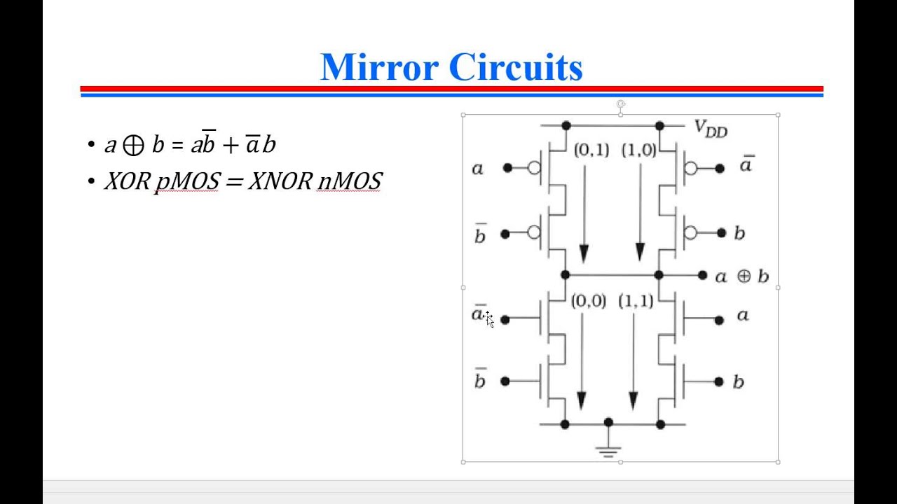
Design a input xor gate using cmos copeland trinceCmos inverter Layout diagram of cmos inverter.
.